Pultruded Fiberglass Grating
Pultruded Manufacturing Process
Pultruded Manufacturing Process and Selection
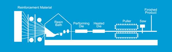
The pultrusion process utilized in the manufacturing of pultruded fiberglass grating and structural shapes is a continuous and automated process where continuous fiberglass rovings and mat are pulled through guides, a resin bath and pre-formers, then wrapped with a synthetic veil before being pulled through a heated die. The individual components of pultruded fiberglass grating – load bars and each piece of the two piece tie-bar are pultruded separately.
Load bars are then cut to specified lengths as they exit the machine. They are drilled at 6” or 12” centers for tie-bar insertion. Once the bars have been drilled they are spaced proportionately for the width of the panel at 3 ft, 4 ft or 5 ft. The two piece locking tie bar assemblies are then inserted creating multiple bonded intersections of load bars and tie bars, thus providing the security of both a mechanically locked and bonded connection. The final step in the process is to seal the cross bars and holes with corrosion resistant epoxy resin.
Pultruded fiberglass grating is uni-directional in strength and provides increased load capacity and very good levels of corrosion resistance. The components (bearing bars and cross bars) which are pulled by machine, provide a higher glass to resin ratio content (65% glass to 35% resin) which
gives it superior load capacity, yet reduces the corrosion resistance when compared to molded fiberglass grating.
Assembled from components, pultruded fiberglass grating can offer a wide variety of panel sizes and substantially reduce "scrap loss" not always possible from molded fiberglass grating panels. In addition, since the pultrusion process is automated, it produces a consistent, high quality finished product.
Advantages of Pultruded Fiberglass Grating:
• High Strength
• Exceptionally High Strength to Weight Ratio
• Lighter Weight
• Accomodates Higher Loads at Greater Spans
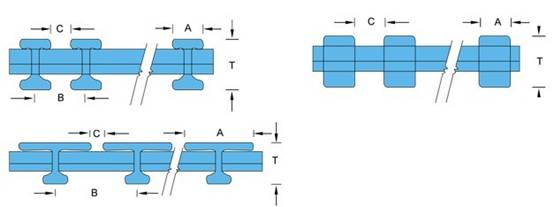
Type |
Height
inch
(mm)
|
Top edge width
(mm) |
Space between
(mm) |
Clearance width
(mm) |
Open area
(%) |
Estimated
Weight
Kg/㎡ |
I-4010 |
25 |
15 |
25 |
10 |
40 |
17.8 |
I-5010 |
25 |
15 |
30 |
15 |
50 |
15.1 |
I-6010A |
25 |
15 |
38 |
23 |
60 |
12.2 |
I-6010B |
25 |
8 |
19.8 |
11.8 |
60 |
13.7 |
I-4015 |
38 |
15 |
25 |
10 |
40 |
22 |
I-5015 |
38 |
15 |
30 |
15 |
50 |
19.1 |
I-6015 |
38 |
15 |
38 |
23 |
60 |
16.2 |
I-4012 |
30 |
15 |
25 |
10 |
40 |
19.1 |
I-5012 |
30 |
15 |
30 |
15 |
50 |
16.1 |
I-6012 |
30 |
15 |
38 |
23 |
60 |
13.1 |
I-40125 |
32 |
15 |
25 |
10 |
40 |
19.8 |
I-50125 |
32 |
15 |
30 |
15 |
50 |
17.4 |
I-60125 |
32 |
15 |
38 |
23 |
60 |
13.5 |
I-4020 |
50 |
15 |
25 |
10 |
40 |
28.5 |
I-5020 |
50 |
15 |
30 |
15 |
50 |
24.2 |
I-6020 |
50 |
15 |
38 |
23 |
60 |
20.1 |
T-1210 |
25 |
38 |
43.4 |
5.4 |
12 |
15.6 |
T-1810 |
25 |
38 |
50.8 |
9.5 |
18 |
13.8 |
T-2510 |
25 |
38 |
50.8 |
12.7 |
25 |
13.6 |
T-3310 |
25 |
41.3 |
61 |
19.7 |
33 |
11.2 |
T-3810 |
25 |
38 |
61 |
23 |
38 |
11.8 |
T-1215 |
38 |
38 |
43.3 |
5.2 |
12 |
19.6 |
T-2515 |
38 |
38 |
50.8 |
12.7 |
25 |
16.7 |
T-3815 |
38 |
38 |
61 |
23 |
38 |
14.2 |
T-3320 |
50 |
25.4 |
38.1 |
12.7 |
33 |
21.7 |
T-5020 |
50 |
25.4 |
50.8 |
25.4 |
50 |
17.2 |
HL-4020 |
50 |
15 |
10 |
10 |
40 |
62.8 |
HL-5020 |
50 |
15 |
15 |
15 |
50 |
52.2 |
HL-6020 |
50 |
15 |
23 |
23 |
60 |
43.5 |